Trails
Reviews
Tips
Community
Deals
Latest
Support
Trails
Find trails
Best bike trails
Destinations
Add a new trail
Reviews
Mountain bike reviews
Components
Tires
Clothing & shoes
Helmets
Accessories
Product news
Community
MTB Clubs
Races & Events
Bike Shops
Tips
Skills
Fitness & Training
Health & Nutrition
Beginners
Repair
Latest Articles
Podcast
Deals
Support Singletracks
Sign in
Create an account
About us
Newsletter signup
How-to
Repair
Trailside Mountain Bike Repair Tips [Podcast #232]
MTB Tips
Enjoying Group Mountain Bike Rides With Slower Friends Can Benefit Everyone
2
Mountain Bikes and Gear
How to Get the Most Money for Your Mountain Bike When it's Time to Sell
1
Drivetrain
Internal Cable Routing Tips for Mountain Bikes
1
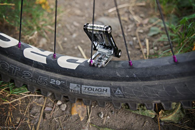
Repair
How to Use the Spoke Wrench on Your Multi-Tool to Trail True a Wheel
MTB Tips
Watch: How to Jump Off Natural Terrain [MTB Skills]
1
Community
Pro Skills: How to Start a Mountain Bike YouTube Channel, Featuring BKXC
1
Derailleur
How to Service Your Shimano Derailleur Clutch
22
Tire Inserts
MTB Tire Insert Mounting Tips: A Bloodshed Minimizing Tutorial
3
MTB Tips
Three Deep Breaths: How to Connect With the Forest That Surrounds Our Beloved Trails
1
Tires All
How to Use Tubeless Mountain Bike Tire Plugs | How to Plug a Hole in a Bike Tire
3
Cockpit
How to Make All of Your Bikes Fit Similarly
MTB Tips
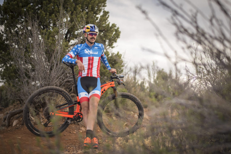
Pro Skills: Smart MTB Recovery Featuring Payson McElveen
MTB Tips
How to Use Energy and Recovery Products Before, During, and After a Mountain Bike Ride
12
Clipless Pedals
How to Ride Clipless Mountain Bike Pedals: Transitioning from Flats
16
Rear Shocks
Watch: Pros and Cons of Running a Coil Shock on a Trail Bike, Plus Setup Tips
Repair
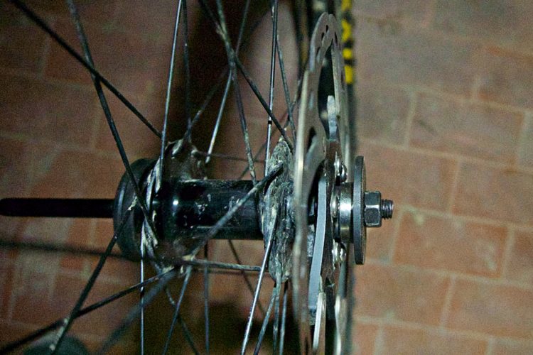
How to Replace Cartridge Bearings in Your Front MTB Wheel
2
MTB Tips
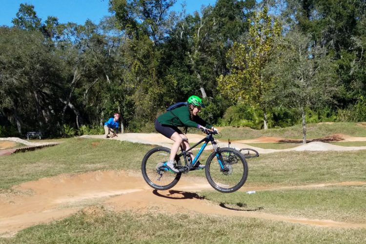
Why You Should Ride Pump Tracks More, and How to Do It
4
MTB Tips
4 Signs You're Ready to Ride More Advanced MTB Trails
2
Derailleur
Troubleshooting Common Rear Derailleur Shifting Problems on a Bike
6
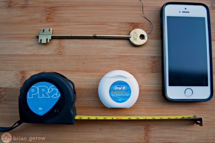
MTB Tips
How to Take Great MTB Photos With a Smartphone
4
MTB Tips
Mountain Bike Skills: The Master List to Learning How to Do Everything
4
MTB Tips
Watch: Tips for Better Balance on the Mountain Bike, From Jeff Lenosky
1
MTB Tips
Watch: Want to Learn to Jump on Your Mountain Bike? Practice Like This Guy!
3
MTB Tips
Watch: Should You Land Front OR Back Wheel First?
Mountain Bike Podcast
Finding More Time to Ride Your Mountain Bike [Podcast #172]
Forks
How A Volume Spacer Changes Your Mountain Bike Suspension
MTB Tips
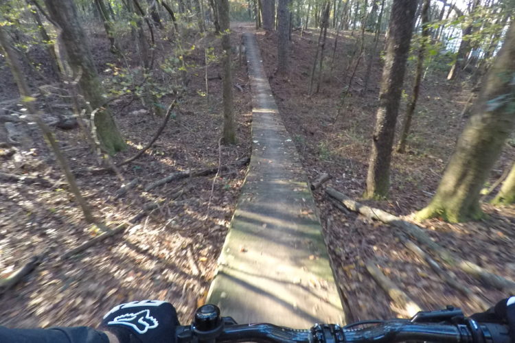
Watch: How to Ride Flat, Rocky Trails, Even in Wet Conditions
1
Mountain Bikes and Gear
Watch: How to Choose Your Next Mountain Bike
4
Culture
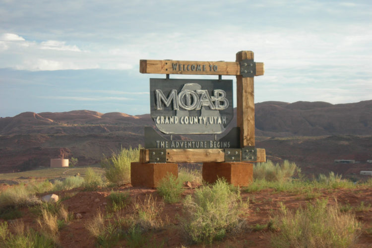
How to Recover When Your Mountain Bike Vacation Goes Off the Rails
3
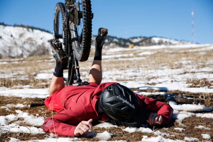
MTB Tips
How to Treat Mountain Bike Injuries
2
Repair
How To Install the OneUp Components EDC Tool System
2
Mountain Bike Podcast
How to Get a Great Bike Fit, and Why It's So Important [Podcast #141]
Mountain Bikes and Gear
Watch: How to Install a New Chain on a Full Suspension Mountain Bike
1
Mountain Bikes and Gear
7 Ways to Get a Great Deal When Buying Your Next Mountain Bike
2
Saddles
How to Set Your Mountain Bike Seat Height... And Why It's So Important
5
MTB Tips
How to Reach Your Annual Mountain Bike Mileage Goal
7
MTB Tips
10 Wilderness Skills Every Adventure Rider Should Have
5
MTB Tips
10 Tips for Mountain Biking in the Rain
4
MTB Tips
Watch: How To Ride Flat Pedals vs. Clipless on Technical Trails
Mountain Bike Podcast
Soft Skills for Mountain Bikers [Podcast #127]
10
Mountain Bike Trails
How to Deal with a Bike Trail Booby Trap
MTB Tips
6 Ways To Keep Yourself Busy While You're Recovering from an Injury
Mountain Bikes and Gear
How To Safely Transport Your Mountain Bikes on a Long Distance Road Trip
4
Community
How To Pick Your Trail Dog
6
Mountain Bikes and Gear
10 Ways to Get the Most out of Demo Days
Mountain Bikes and Gear
How To Repair a Carbon Bike Frame at Home
3
Mountain Bikes and Gear
Watch: How To Build a Fork Mount Bike Rack for $20 in 30 Minutes
1
1
2
3
4
»


 2
2